


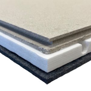
Board Material


Water Underfloor Heating
How much pipe will I need to cover my room for Water based UFH?
To calculate how much pipe is required, you will need to divide the area of your room(s) by the pipe spacing you require.
What should be the maximum circuit length?
For 15mm, 16mm and 20mm Pipe:
To avoid excessive temperature and pressure drops, it is recommended that a maximum circuit length of 100m is used.
150mm Pipe Spacing
If you are planning 150mm Pipe Spacing (for high heat loss area such as a conservatories, extensions and external buildings), you will need approximately 6.67m of pipe for each m². With this option, a 100m coil of pipe will cover up to 15m².
200mm Pipe Spacing
If you are planning 200mm (standard pipe spacing for internal well insulated areas) is specified, you will need approximately 5m of pipe for each m². This would mean each 100m circuit will cover up to 20m².
For 12mm Pipe:
To avoid excessive temperature and pressure drops, it is recommended that a maximum circuit length of 80m is used.
150mm Pipe Spacing
If you are planning 150mm Pipe Spacing (for high heat loss area such as a conservatories, extensions and external buildings), you will need approximately 6.67m of pipe for each m². With this option, a 80m coil of pipe will cover up to 12m².
200mm Pipe Spacing (Not recommended, due to low heat output)
If you are planning 200mm (standard pipe spacing for internal well insulated areas) is specified, you will need approximately 5m of pipe for each m². This would mean each 80m circuit will cover up to 16m².
Note: You might need to allow a few extra meters of pipe for feed and return from and the manifold.
How Many Clips Would I Need?
Simply multiply the pipe length by 2. For example; for 100m length of pipe, you will need 200 clips.
How Many Clip Rails Do I Need?
An easy way to work this out is to take the area of room you are covering and multiply by 1.5. So if you have a 20m2 room then you will require 20×1.5 clip rails which is 30 clip rails
How Many Screws & Washers Do I Need To Affix Cement Overlay Boards?
For the cement boards we would suggest as well as adhesive in addition fix with 35mm diameter washers and suitable screws using approximately 8 fixings per panel.

How To Clear A Blockage On Grundfos UPM3 Series Pumps
Instructions for Unjamming a GRUNDFOS UPM3 Pump:
![]()
If your GRUNDFOS UPM3 pump has been idle for an extended period, such as during the summer months, it may encounter difficulty running when powered on again due to debris buildup within the pump, hindering the rotor’s movement. Here’s how to address this issue:
- Listen for Clicking: Upon attempting to start the pump, you may hear repeated clicking sounds, indicating the pump’s built-in mechanism is trying to free itself.
- Attempt Automatic Release: Allow the pump to try freeing itself by listening for the clicking noise. Sometimes, this action alone can resolve the issue.
- Manual Intervention: If the pump remains jammed despite the automatic attempts, you may need to manually turn the rotor. Contrary to popular belief, the UPM3 pump can indeed be turned manually.
- Locate Pump Head Hole: In the center of the pump head, identify a hole. Insert a long shank CROSS HEAD screwdriver into this hole, positioning the tip onto the rotor shaft.
- Engage and Turn: Apply pressure and turn the screwdriver to engage the shaft onto the rotor. Initially, the shaft may turn easily, but it needs to be pushed firmly and turned to fully engage with the rotor. Once engaged, you can turn and free the rotor.
- Clean the Pump: If manual intervention fails due to excessive debris, isolate the pump using the valves and easily remove the head for cleaning. Ensure the system water is kept clean, and use a suitable inhibitor in the correct dilution to prevent future issues.
- Preventative Measures: To avoid similar problems in the future, consider turning on the pump at regular intervals during periods of inactivity. Alternatively, install controls with a built-in pump exercise function and utilize this feature regularly for optimal pump performance.
By following these steps, you can effectively free a jammed rotor in your GRUNDFOS UPM3 pump and maintain its functionality for smooth operation.
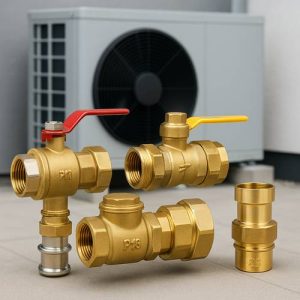
Understading The Numbers On Circulating Pumps - The Basics
Pumps often have codes on them such as in the case of a Grundfos Auto it will have 25/70-130.
-
- The first number 25 refers to the approximate pump inlet diameter
- The second number refers to the head of pressure in metres where 70 in this case is 7m, the maximum height that the pump can push water up to
- The third number ‘130’ refers to the fitting across faces of the pump in this case 130mm which is typical of these pumps
Is a Floor Sensor Necessary for Wet Underfloor Heating?
Not always. Underfloor heating (UFH) can function with just an air sensor, but in certain situations, a floor sensor is recommended. The primary reason for installing a floor sensor is to protect your floor coverings from excessive heat, ensuring durability and optimal performance.
Does planning ufh using a spiral pattern use less or more pipe than using a serpentine pattern
When planning underfloor heating (UFH), the spiral (or helical) pattern generally uses more pipe than a serpentine (or meandering) pattern.
Here’s why:
1. Pipe Length
-
-
Spiral Pattern: Designed to distribute heat evenly by running both the flow and return pipes side by side. This ensures that no part of the floor is significantly warmer or cooler than others. To achieve this, the layout often involves tighter bends and more looping, which increases the total pipe length.
-
Serpentine Pattern: Runs in a back-and-forth (zigzag) fashion. It’s simpler and tends to use less pipe because it’s more direct, but it can lead to uneven heat distribution — warmer at the start of the run, cooler at the end.
-
2. Heat Distribution
-
-
Spiral = More uniform heat, better comfort, and better suited to large or high-load areas.
-
Serpentine = Less uniform heat, better for small or low-load areas, or where simplicity and pipe economy are key.
-
Summary:
| Pattern | Pipe Usage | Heat Distribution |
|---|---|---|
| Spiral | More | Even |
| Serpentine | Less | Uneven |
Heat Output, Flow Rates & Which Pipe Size Is Best 12mm or 16mm?
Overall Recommendation
-
- 12mm MLCP is ideal for retrofit and low-profile UFH systems.
- 16mm MLCP is generally the better choice for maximum heat output and system efficiency.
For most new-build underfloor heating installations, 16mm MLCP remains the preferred option.
See the full article on which pipe size is best for your underfloor heating system.
Heatmiser Specific
What cable type/brand and thickness is required for connecting neostats to wiring centre
You must fit mains cable in accordance to local install regulations. We normally recommend for our 3 amp max units, 3 core plus earth (4 core) 1.5mm cable.
Can I lock a NeoStat down via the app?
Yes, you can lock the Heatmiser neoStat keypad directly via the neoApp.
Here is how to lock the neoStat using the app:
- For 1 Zone: Navigate to the Zone list, select the specific Zone, and press the Padlock Icon to enter a PIN number.
- For Multiple Zones: Go to the Zone list, select “Lock”, enter a PIN, and select the zones you wish to lock.
Key Details:
- Purpose: Locking restricts unauthorized users from changing the temperature or settings directly on the wall-mounted thermostat.
- Unlock Process: To unlock it, you can use the same method in the app or by entering the PIN on the device itself.
- Alternative: You can also lock the device directly by navigating to “Hold” on the neoStat screen and holding the tick button for 10 seconds.
Note: If you forget your PIN code, you will need to contact Heatmiser support for assistance.
What connection range do the Heatmiser NeoAir Thermostats typically have?
Short answer:
👉 Typical reliable range is ~20–40 m in real homes, up to ~100 m in ideal open space.
Here’s the accurate breakdown for Heatmiser neoAir RF thermostats 👇
📡 Real-world RF range
🔹 Open space (best case)
- Up to ~100 metres line-of-sight
👉 This is a lab/ideal figure (no walls, no interference).
🔹 Typical house (what you actually get)
- Around 20–40 metres between devices
Why it drops:
- Brick / concrete walls
- Floors (especially steel-reinforced)
- Boilers, wiring centres, metal cupboards
- WiFi / RF interference
👉 In most UK homes, expect:
- Same floor: usually fine
- Across floors: sometimes borderline without help
🔹 With mesh / system components
The neo system can extend range depending on setup:
- ~20 m between “hops” in a mesh network
- Mains-powered devices (like neoStat or hub-connected devices) can help relay signals
👉 Important:
- neoAir itself does NOT repeat signals
- So battery thermostats alone = weaker overall coverage
🔹 Extending the range
If distance is an issue, Heatmiser provides:
Boost V2 (repeater)
- Adds ~another 20 m per repeater “hop”
- Can chain multiple if needed
Wired devices (neoStat)
- Act as signal relays in the Neo system
🧠 Practical rule of thumb
- Small house / flat: no issues
- Medium house (2-storey): usually fine, maybe 1 repeater
- Large house / thick walls / plant room: plan for Boost units
🔎 Bottom line
- Max theoretical: ~100 m
- Realistic working range: ~20–40 m
- Extendable: yes, via repeaters or mesh
How many actuators can I connect to a zone?
You can connect up to 4 actuators to one zone on the Heatmiser wiring centre. You should ensure the total load on the wiring centre is <5A
Chipboard System Installation
How Much PVA Chipboard Joint Glue Do I Need?
To glue the joints of the chipboard overlay together we recommend using our D3 PVA Glue 1KG bottle.
1 Bottle will cover approximate joints for 30m2 of floor area.
How many joist fixing screws will I need
The boards should also be glued and screwed to the joists, with 2x 80mm fixings required at each cross section with the joists below (150mm in from either side of the 600mm width). This equates to 12 x 80mm screws per board.
Note: Required number of screws to affix routed chipboard to joist is 12 per board for 400m centre joists, 8 per board for 600mm centre joists.
A box of 200 screws will cover
-
- 16 boards for 400mm joist spacing
- 25 boards for 600 mm joist spacing
How Many Overlay Screws Will I need?
The cement overlay boards are 1200x900mm and it is advised that you screw down every 150mm using 25mm screws on a grid pattern.
This equates to c42 screws per board
A box of 200 5mm x 25mm screws will cover 4.75 Resobacker overlay boards
How Much Glue Will I Need To Affix Overlay Boards
You must use the manufacture, Resonate’s, approved MS Polymer adhesive that currently comes in 290ml cartridges which will cover approximately 1.8m2 when applied with a 3mm bead.
so divide your floor area by this to work out how many bottles you require. Example 18m2 of floor area would require 10 x 290ml cartridges of glue.
Electric Underfloor Heating
Is electric underfloor heating expensive to run?
This is the most common question we get and the simple answer is, that the running costs are determined by many different factors so it is difficult to generalise. When the systems are used in a well-insulated building (in line with current building regulations) the running costs are usually very low, the thermostatic control in each room/zone means that you only use just enough energy to maintain your desired room temperature. Based on the default thermostat settings, a 1kw system will cost approximately £0.40 a day, based on an average house with an average level of insulation
How warm will the floor get?
Our systems are designed so that the floor surface will feel comfortably warm , but will never get too hot to walk on! The thermostat regulates the floor temperature by turning the system off when the floor gets to the required temperature, then back on as the floor begins to cool – thus keeping a constant temperature. It does this up to 3 times per minute for optimum control and maximum energy efficiency.